-
call us
022 23857766 \ 022 67437326 -
send us mail
sales@globalstainless.co.in
| Normal Pipe Size | D | K | L | A | C | N1 | N2 | B | H1 | H2 | R1 | R2 | HOLES | |
|---|---|---|---|---|---|---|---|---|---|---|---|---|---|---|
| Inch | Millimeter | |||||||||||||
| ½” | 15 | 95.3 | 66.8 | 14.5 | 21.3 | 6.4 | 27.0 | 33.3 | 22.4 | 9.5 | 22.2 | 6.4 | 1.6 | 4 |
| ¾” | 20 | 101.6 | 73.2 | 14.5 | 26.7 | 6.4 | 33.3 | 38.1 | 27.7 | 11.1 | 22.2 | 6.4 | 1.6 | 4 |
| 1″ | 25 | 114.3 | 82.6 | 14.5 | 33.5 | 7.2 | 42.9 | 47.6 | 34.6 | 11.1 | 22.2 | 6.4 | 1.6 | 4 |
| 1 ¼” | 32 | 120.7 | 87.4 | 14.5 | 42.2 | 7.9 | 49.2 | 55.6 | 43.2 | 11.1 | 25.4 | 6.4 | 1.6 | 4 |
| 1 ½” | 40 | 133.4 | 98.6 | 14.5 | 48.3 | 8.7 | 58.7 | 61.9 | 49.5 | 12.7 | 28.6 | 6.4 | 1.6 | 4 |
| 2″ | 50 | 152.4 | 114.3 | 17.5 | 60.5 | 9.5 | 69.9 | 74.6 | 62.0 | 12.7 | 28.6 | 6.4 | 1.6 | 4 |
| 2 ½” | 65 | 165.1 | 127.0 | 17.5 | 73.2 | 10.3 | 82.6 | 90.5 | 74.7 | 15.9 | 31.8 | 6.4 | 1.6 | 4 |
| 3″ | 80 | 184.2 | 146.1 | 17.5 | 88.9 | 11.1 | 101.6 | 106.4 | 90.7 | 15.9 | 34.9 | 6.4 | 1.6 | 4 |
| 3 ½” | 88 | 203.2 | 165.1 | 17.5 | 101.6 | 11.9 | 114.3 | 119.1 | 103.4 | 17.5 | 34.9 | 6.4 | 1.6 | 4 |
| 4″ | 100 | 215.9 | 177.8 | 17.5 | 114.3 | 12.7 | 130.2 | 133.4 | 116.1 | 19.1 | 41.3 | 9.5 | 3.2 | 4 |
| 5″ | 125 | 254.0 | 209.6 | 17.5 | 141.2 | 14.3 | 152.4 | 160.3 | 143.8 | 19.1 | 44.5 | 9.5 | 3.2 | 8 |
| 6″ | 150 | 279.4 | 235.0 | 17.5 | 168.4 | 17.5 | 184.2 | 185.7 | 171.7 | 19.1 | 47.6 | 9.5 | 3.2 | 8 |
| 8″ | 200 | 336.6 | 292.1 | 17.5 | 219.2 | 19.1 | 241.3 | 241.3 | 221.5 | 22.2 | 50.8 | 9.5 | 3.2 | 8 |
| 10″ | 250 | 406.4 | 355.6 | 22.2 | 273.1 | 22.2 | 292.1 | 298.5 | 276.4 | 27.0 | 63.5 | 9.5 | 3.2 | 8 |
| 12″ | 300 | 457.2 | 406.4 | 22.2 | 323.9 | 25.4 | 342.9 | 349.3 | 325.9 | 28.6 | 69.9 | 9.5 | 4.8 | 12 |
| 14″ | 350 | 527.1 | 469.9 | 25.4 | 355.6 | 28.6 | 406.4 | - | 359.2 | - | 73.0 | 9.5 | 4.8 | 12 |
| 16″ | 400 | 577.9 | 520.7 | 25.4 | 406.4 | 31.8 | 431.8 | - | 410.5 | - | - | - | - | 12 |
| 18″ | 450 | 641.4 | 584.2 | 25.4 | 457.2 | 34.9 | - | - | 461.8 | - | - | - | - | 12 |
| 20″ | 500 | 704.9 | 641.4 | 25.4 | 508.0 | 38.1 | - | - | 513.1 | - | - | - | - | 16 |
| 24″ | 600 | 825.5 | 755.7 | 28.7 | 609.6 | 47.6 | - | - | 616.0 | - | - | - | - | 16 |
|
Temper. |
Max Hydraulic |
||||||||
|
0°F to 450°F |
500°F |
600°F |
700°F |
800°F |
850°F |
900°F |
|||
|
FLANGE TABLES |
-18°C to 230°C |
260°C |
315°C |
370°C |
425°C |
450°C |
480°C |
||
|
Test Pressure |
|||||||||
|
D |
100 |
95 |
80 |
65 |
50 |
– |
– |
150 |
|
|
E |
200 |
185 |
155 |
130 |
100 |
– |
– |
300 |
|
|
F |
300 |
280 |
235 |
195 |
150 |
– |
– |
450 |
|
|
H |
500 |
465 |
395 |
320 |
250 |
180 |
115 |
750 |
|
|
J |
700 |
650 |
550 |
450 |
350 |
255 |
160 |
1050 |
|
|
K |
900 |
835 |
705 |
580 |
450 |
325 |
205 |
1350 |
|
|
R |
1200 |
1115 |
945 |
770 |
600 |
435 |
275 |
1800 |
|
|
S |
1800 |
1670 |
1415 |
1155 |
900 |
655 |
415 |
2700 |
|
|
T |
2800 |
2600 |
2200 |
1800 |
1400 |
1025 |
645 |
4200 |
|
| Specification : | BS 10 Flanges |
| Standard : | ISO Flange, JIS Flange, ASME B16.47 (Series A, Series B) Flange, MSS SP44 Flange, EN-1092 Flange, BS10 Flange, ASME B16.38 Flange, UNI Flange, PN Flange, ASME B16.5 Flange, AWWA Flange, DIN Flange, GOST Flange |
| Pressure Rating Tables: | Class 150 LBS, Class 300 LBS, Class 600 LBS, Class 900 LBS, Class 1500 LBS, Class 2500 LBS |
| Production Process: | Forged, Heat Treated and Machined |
| Application: | Water Pipeline Industry Nuclear Power Plant Chemical Industry Oil And Gas Industry Fabrication Industry Natural Gas Industry |
| Coating Flange Faces : | Anti-rust Paint, Zinc Plated, Cold and Hot Dip Galvanized, Oil Black Paint, Yellow Transparent |
| Size Chart : | 1/2″ (15 NB) To 48″ (1200NB) |
| Supporting Flange Material: | Flange Bolts, Gasket, Ring Joint |
| Machining Equipment: | Press machine, Pushing Machine, Electric bevelling machine, Bending machine, Sand-blasting machine etc |
| Design For Size: | ASA, PN, JIS, DIN, BS, ANSI, ASME, EN |
| Common Types of Flanges Dimensions: | Class 150 RTJ Flanges 300 LB WNRF Class 900 SORF 1500# BLRF Class 2500 BLRF |
| Connect Type Type: | LMF, RF, RTJ, SMF, LJF, FF |
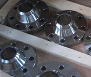
BS 10 Table E Pipe Flanges
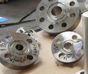
BS 10 Table D Pipe Flanges
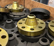
BS 10 Table F Pipe Flanges
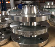
Stainless Steel BS 10 Flanges table
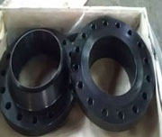
ANSI B16.5 Class 150 bs 10 standard Flange
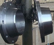
ASTM A182 SS bs 10 table d Flange
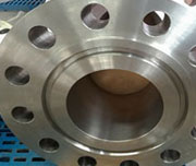
Alloy Steel bs 10 table f Flange
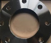
Nickel Alloy 200 BS 10 Table F Pipe Flange
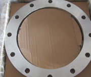
DIN86029 PN10 BS 10 Flange
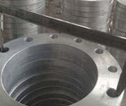
Duplex Steel BS 10 Table E Flange
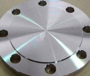
Alloy Steel bs 10 table f Flange
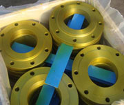
Inconel Flange as per BS 10 Table D
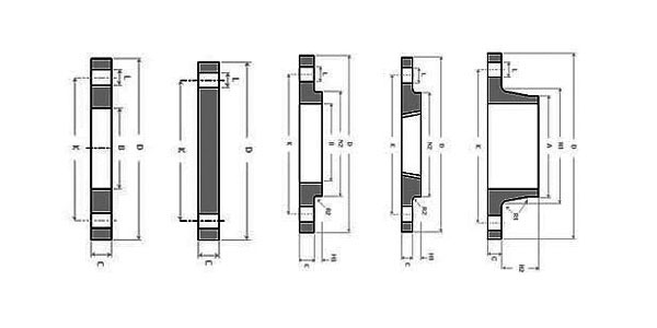
| Normal Pipe Size | D | K | L | A | C | N1 | N2 | B | H1 | H2 | R1 | R2 | HOLES | |
|---|---|---|---|---|---|---|---|---|---|---|---|---|---|---|
| IN | mm | |||||||||||||
| ½” | 15 | 95.3 | 66.8 | 14.5 | 21.3 | 4.8 | 27.0 | 33.3 | 22.4 | 9.5 | 22.2 | 6.4 | 1.6 | 4 |
| ¾” | 20 | 101.6 | 73.2 | 14.5 | 26.7 | 4.8 | 33.3 | 38.1 | 27.7 | 11.1 | 22.2 | 6.4 | 1.6 | 4 |
| 1″ | 25 | 114.3 | 82.6 | 14.5 | 33.5 | 4.8 | 42.9 | 47.6 | 34.6 | 11.1 | 22.2 | 6.4 | 1.6 | 4 |
| 1 ¼” | 32 | 120.7 | 87.4 | 14.5 | 42.2 | 6.4 | 49.2 | 55.6 | 43.2 | 11.1 | 25.4 | 6.4 | 1.6 | 4 |
| 1 ½” | 40 | 133.4 | 98.6 | 14.5 | 48.3 | 6.4 | 58.7 | 61.9 | 49.5 | 12.7 | 28.6 | 6.4 | 1.6 | 4 |
| 2″ | 50 | 152.4 | 114.3 | 17.5 | 60.5 | 7.9 | 69.9 | 74.6 | 62.0 | 12.7 | 28.6 | 6.4 | 1.6 | 4 |
| 2 ½” | 65 | 165.1 | 127.0 | 17.5 | 73.2 | 7.9 | 82.6 | 90.5 | 74.7 | 15.9 | 31.8 | 6.4 | 1.6 | 4 |
| 3″ | 80 | 184.2 | 146.1 | 17.5 | 88.9 | 9.7 | 101.6 | 106.4 | 90.7 | 15.9 | 34.9 | 6.4 | 1.6 | 4 |
| 3 ½” | 88 | 203.2 | 165.1 | 17.5 | 101.6 | 9.7 | 114.3 | 119.1 | 103.4 | 17.5 | 34.9 | 6.4 | 1.6 | 4 |
| 4″ | 100 | 215.9 | 177.8 | 17.5 | 114.3 | 9.7 | 130.2 | 133.4 | 116.1 | 19.1 | 41.3 | 9.5 | 3.2 | 4 |
| 5″ | 125 | 254.0 | 209.6 | 17.5 | 141.2 | 12.7 | 152.4 | 160.3 | 143.8 | 19.1 | 44.5 | 9.5 | 3.2 | 8 |
| 6″ | 150 | 279.4 | 235.0 | 17.5 | 168.4 | 12.7 | 184.2 | 185.7 | 171.7 | 19.1 | 47.6 | 9.5 | 3.2 | 8 |
| 8″ | 200 | 336.6 | 292.1 | 17.5 | 219.2 | 12.7 | 241.3 | 241.3 | 221.5 | 22.2 | 50.8 | 9.5 | 3.2 | 8 |
| 10″ | 250 | 406.4 | 355.6 | 22.2 | 273.1 | 16.0 | 292.1 | 298.5 | 276.4 | 27.0 | 63.5 | 9.5 | 3.2 | 8 |
| 12″ | 300 | 457.2 | 406.4 | 22.2 | 323.9 | 19.1 | 342.9 | 349.3 | 325.9 | 28.6 | 69.9 | 9.5 | 4.8 | 12 |
| 14″ | 350 | 527.1 | 469.9 | 25.4 | 355.6 | 22.2 | 406.4 | - | 359.2 | - | 73.0 | 9.5 | 4.8 | 12 |
| 16″ | 400 | 577.9 | 520.7 | 25.4 | 406.4 | 22.2 | - | - | 410.5 | - | - | - | - | 12 |
| 18″ | 450 | 641.4 | 584.2 | 25.4 | 457.2 | 25.4 | - | - | 461.8 | - | - | - | - | 12 |
| 20″ | 500 | 704.9 | 641.4 | 25.4 | 508.0 | 28.6 | - | - | 513.1 | - | - | - | - | 16 |
| 24″ | 600 | 825.5 | 755.7 | 28.7 | 609.6 | 31.8 | - | - | 616.0 | - | - | - | - | 16 |
| Normal Pipe Size | D | K | L | A | C | N1 | N2 | B | H1 | H2 | R1 | R2 | HOLES | |
|---|---|---|---|---|---|---|---|---|---|---|---|---|---|---|
| Inch | Millimeter | |||||||||||||
| ½” | 15 | 95.3 | 66.8 | 14.5 | 21.3 | 6.4 | 27.0 | 33.3 | 22.4 | 9.5 | 22.2 | 6.4 | 1.6 | 4 |
| ¾” | 20 | 101.6 | 73.2 | 14.5 | 26.7 | 6.4 | 33.3 | 38.1 | 27.7 | 11.1 | 22.2 | 6.4 | 1.6 | 4 |
| 1″ | 25 | 114.3 | 82.6 | 14.5 | 33.5 | 7.2 | 42.9 | 47.6 | 34.6 | 11.1 | 22.2 | 6.4 | 1.6 | 4 |
| 1 ¼” | 32 | 120.7 | 87.4 | 14.5 | 42.2 | 7.9 | 49.2 | 55.6 | 43.2 | 11.1 | 25.4 | 6.4 | 1.6 | 4 |
| 1 ½” | 40 | 133.4 | 98.6 | 14.5 | 48.3 | 8.7 | 58.7 | 61.9 | 49.5 | 12.7 | 28.6 | 6.4 | 1.6 | 4 |
| 2″ | 50 | 152.4 | 114.3 | 17.5 | 60.5 | 9.5 | 69.9 | 74.6 | 62.0 | 12.7 | 28.6 | 6.4 | 1.6 | 4 |
| 2 ½” | 65 | 165.1 | 127.0 | 17.5 | 73.2 | 10.3 | 82.6 | 90.5 | 74.7 | 15.9 | 31.8 | 6.4 | 1.6 | 4 |
| 3″ | 80 | 184.2 | 146.1 | 17.5 | 88.9 | 11.1 | 101.6 | 106.4 | 90.7 | 15.9 | 34.9 | 6.4 | 1.6 | 4 |
| 3 ½” | 88 | 203.2 | 165.1 | 17.5 | 101.6 | 11.9 | 114.3 | 119.1 | 103.4 | 17.5 | 34.9 | 6.4 | 1.6 | 4 |
| 4″ | 100 | 215.9 | 177.8 | 17.5 | 114.3 | 12.7 | 130.2 | 133.4 | 116.1 | 19.1 | 41.3 | 9.5 | 3.2 | 4 |
| 5″ | 125 | 254.0 | 209.6 | 17.5 | 141.2 | 14.3 | 152.4 | 160.3 | 143.8 | 19.1 | 44.5 | 9.5 | 3.2 | 8 |
| 6″ | 150 | 279.4 | 235.0 | 17.5 | 168.4 | 17.5 | 184.2 | 185.7 | 171.7 | 19.1 | 47.6 | 9.5 | 3.2 | 8 |
| 8″ | 200 | 336.6 | 292.1 | 17.5 | 219.2 | 19.1 | 241.3 | 241.3 | 221.5 | 22.2 | 50.8 | 9.5 | 3.2 | 8 |
| 10″ | 250 | 406.4 | 355.6 | 22.2 | 273.1 | 22.2 | 292.1 | 298.5 | 276.4 | 27.0 | 63.5 | 9.5 | 3.2 | 8 |
| 12″ | 300 | 457.2 | 406.4 | 22.2 | 323.9 | 25.4 | 342.9 | 349.3 | 325.9 | 28.6 | 69.9 | 9.5 | 4.8 | 12 |
| 14″ | 350 | 527.1 | 469.9 | 25.4 | 355.6 | 28.6 | 406.4 | - | 359.2 | - | 73.0 | 9.5 | 4.8 | 12 |
| 16″ | 400 | 577.9 | 520.7 | 25.4 | 406.4 | 31.8 | 431.8 | - | 410.5 | - | - | - | - | 12 |
| 18″ | 450 | 641.4 | 584.2 | 25.4 | 457.2 | 34.9 | - | - | 461.8 | - | - | - | - | 12 |
| 20″ | 500 | 704.9 | 641.4 | 25.4 | 508.0 | 38.1 | - | - | 513.1 | - | - | - | - | 16 |
| 24″ | 600 | 825.5 | 755.7 | 28.7 | 609.6 | 47.6 | - | - | 616.0 | - | - | - | - | 16 |
|
NPS |
Diameter of |
Diameter of |
No. of |
Diameter of |
Thick. |
|||||||||||||
|
NPS |
Flange |
Bolt Circle |
Bolt |
Bolt |
||||||||||||||
|
1/2" |
114.3 |
82.6 |
4 |
15.9 |
12.7 |
|||||||||||||
|
3/4" |
114.3 |
82.6 |
4 |
15.9 |
12.7 |
|||||||||||||
|
1" |
120.78 |
87.3 |
4 |
15.9 |
14.3 |
|||||||||||||
|
1 1/4" |
133.4 |
98.4 |
4 |
15.9 |
17.5 |
|||||||||||||
|
1 1/2" |
139.7 |
104.8 |
4 |
15.9 |
17.5 |
|||||||||||||
|
2" |
165.1 |
127.0 |
4 |
15.9 |
19.1 |
|||||||||||||
|
2 1/2" |
184.2 |
146.1 |
8 |
15.9 |
19.1 |
|||||||||||||
|
3" |
203.2 |
165.1 |
8 |
15.9 |
22.2 |
|||||||||||||
|
3 1/2" |
215.9 |
177.8 |
8 |
15.9 |
22.2 |
|||||||||||||
|
4" |
228.6 |
190.5 |
8 |
15.9 |
25.4 |
|||||||||||||
|
5" |
279.4 |
235.0 |
8 |
19.1 |
28.6 |
|||||||||||||
|
6" |
304.8 |
260.4 |
12 |
19.1 |
28.6 |
|||||||||||||
|
7" |
336.6 |
292.1 |
12 |
19.1 |
31.8 |
|||||||||||||
|
8" |
368.3 |
323.9 |
12 |
19.1 |
31.8 |
|||||||||||||
|
9" |
406.4 |
355.6 |
12 |
22.2 |
34.9 |
|||||||||||||
|
10" |
431.8 |
381.0 |
12 |
22.2 |
34.9 |
|||||||||||||
|
12" |
489.0 |
438.2 |
16 |
22.2 |
38.1 |
|||||||||||||
|
14" |
552.5 |
495.3 |
16 |
25.4 |
41.3 |
|||||||||||||
|
16" |
609.6 |
552.5 |
20 |
25.4 |
44.5 |
|||||||||||||
|
18" |
673.1 |
609.6 |
20 |
28.6 |
47.6 |
|||||||||||||
|
20" |
736.6 |
673.1 |
24 |
28.6 |
50.8 |
|||||||||||||
|
24" |
850.9 |
781.1 |
24 |
31.8 |
57.2 |
|||||||||||||
| NOMINAL BORE 15 | FLANGE DIAM. IN MILLIMETER | PCD | BOLTS | BOLTSIZE | HOLE SIZE | THICK. |
|---|---|---|---|---|---|---|
| Table D | 3 3/4 / 95 | 2 5/8 / 67 | 4 | 1/2 | 9/16 / 14 | 3/8 / 10 |
| Table E | 3 3/4 / 95 | 2 5/8 / 67 | 4 | 1/2 | 9/16 / 14 | 3/8 / 10 |
| Table F | 3 3/4 / 95 | 2 5/8 / 67 | 4 | 1/2 | 9/16 / 14 | 3/8 / 10 |
| Table H | 4 1/2 / 114 | 3 1/4 / 83 | 4 | 5/8 | 11/16 / 17 | 1/2 / 13 |
| Table J | 4 1/2 / 114 | 3 1/4 / 83 | 4 | 5/8 | 11/16 / 17 | 5/8 / 16 |
| Table K | 4 1/2 / 114 | 3 1/4 / 83 | 4 | 5/8 | 11/16 / 17 | 3/4 / 19 |
| NOMINAL BORE 20 | FLANGE DIAME. in mm | PCD | BOLTS | BOLTSIZE | HOLE SIZE | THICK. |
| Table D | 4 / 102 | 2 7/8 / 73 | 4 | 1/2 | 9/16 / 14 | 3/8 / 10 |
| Table E | 4 / 102 | 2 7/8 / 73 | 4 | 1/2 | 9/16 / 14 | 3/8 / 10 |
| Table F | 4 / 102 | 2 7/8 / 73 | 4 | 1/2 | 9/16 / 14 | 3/8 / 10 |
| Table H | 4 1/2 / 114 | 3 1/4 / 83 | 4 | 5/8 | 11/16 / 17 | 1/2 / 13 |
| Table J | 4 1/2 / 114 | 3 1/4 / 83 | 4 | 5/8 | 11/16 / 17 | 5/8 / 16 |
| Table K | 4 1/2 / 114 | 3 1/4 / 83 | 4 | 5/8 | 11/16 / 17 | 3/4 / 19 |
| NOMINAL BORE 25 | FLANGE DIAME. | PCD | BOLTS | BOLTSIZE | HOLE SIZE | THICK. |
| Table D | 4 1/2 / 114 | 3 1/4 / 83 | 4 | 1/2 | 9/16 / 14 | 3/8 / 10 |
| Table E | 4 1/2 / 114 | 3 1/4 / 83 | 4 | 1/2 | 9/16 / 14 | 3/8 / 10 |
| Table F | 4 3/4 / 121 | 3 7/16 / 87 | 4 | 5/8 | 9/16 / 14 | 3/8 / 10 |
| Table H | 4 3/4 / 121 | 3 7/16 / 87 | 4 | 5/8 | 11/16 / 17 | 9/16 / 14 |
| Table J | 4 3/4 / 121 | 3 7/16 / 87 | 4 | 5/8 | 11/16 / 17 | 3/4 / 19 |
| Table K | 5 / 127 | 3 3/4 / 95 | 4 | 5/8 | 11/16 / 17 | 7/8 / 22 |
| NOMINAL BORE 32 | FLANGE DIAME. | PCD | BOLTS | BOLTSIZE | HOLE SIZE | THICK. |
| Table D | 4 3/4 / 121 | 3 7/16 / 87 | 4 | 1/2 | 9/16 / 14 | 1/2 / 13 |
| Table E | 4 3/4 / 121 | 3 7/16 / 87 | 4 | 1/2 | 9/16 / 14 | 1/2 / 13 |
| Table F | 5 1/4 / 133 | 3 7/8 / 98 | 4 | 5/8 | 11/16 / 17 | 1/2 / 13 |
| Table H | 5 1/4 / 133 | 3 7/8 / 98 | 4 | 5/8 | 11/16 / 17 | 11/16 / 17 |
| Table J | 5 1/4 / 133 | 3 7/8 / 98 | 4 | 5/8 | 11/16 / 17 | 3/4 / 19 |
| Table K | 5 1/4 / 133 | 3 7/8 / 98 | 4 | 5/8 | 11/16 / 17 | 7/8 / 22 |
| NOMINAL BORE 40 | FLANGE DIAME. | PCD | BOLTS | BOLTSIZE | HOLE SIZE | THICK. |
| Table D | 5 1/4 / 133 | 3 7/8 / 98 | 4 | 1/2 | 9/16 / 14 | 1/2 / 13 |
| Table E | 5 1/4 / 133 | 3 7/8 / 98 | 4 | 1/2 | 9/16 / 14 | 1/2 / 13 |
| Table F | 5 1/2 / 140 | 4 1/8 / 105 | 4 | 5/8 | 11/16 / 17 | 1/2 / 13 |
| Table H | 5 1/2 / 140 | 4 1/8 / 105 | 4 | 5/8 | 11/16 / 17 | 11/16 / 17 |
| Table J | 5 1/2 / 140 | 4 1/8 / 105 | 4 | 5/8 | 11/16 / 17 | 7/8 / 22 |
| Table K | 6 / 152 | 4 1/2 / 114 | 4 | 3/4 | 7/8 / 22 | 1 / 25 |
| NOMINAL BORE 50 | FLANGE DIAME. | PCD | BOLTS | BOLTSIZE | HOLE SIZE | THICK. |
| Tables D | 6 / 152 | 4 1/2 / 114 | 4 | 5/8 | 11/16 / 17 | 9/16 / 14 |
| Tables E | 6 / 152 | 4 1/2 / 114 | 4 | 5/8 | 11/16 / 17 | 9/16 / 14 |
| Tables F | 6 1/2 / 165 | 5 / 127 | 4 | 5/8 | 11/16 / 17 | 5/8 / 16 |
| Tables H | 6 1/2 / 165 | 5 / 127 | 4 | 5/8 | 11/16 / 17 | 3/4 / 19 |
| Tables J | 6 1/2 / 165 | 5 / 127 | 4 | 3/4 | 7/8 / 22 | 1 / 25 |
| Tables K | 6 1/2 / 165 | 5 / 127 | 8 | 5/8 | 11/16 / 17 | 1 / 25 |
| NOMINAL BORE 65 | FLANGE DIAME. | PCD | BOLTS | BOLTSIZE | HOLE SIZE | THICK. |
| Tables D | 6 1/2 / 165 | 5 / 127 | 4 | 5/8 | 11/16 / 17 | 9/16 / 14 |
| Tables E | 6 1/2 / 165 | 5 / 127 | 4 | 5/8 | 11/16 / 17 | 9/16 / 14 |
| Tables F | 7 1/4 / 184 | 5 3/4 / 146 | 8 | 5/8 | 11/16 / 17 | 5/8 / 16 |
| Tables H | 7 1/4 / 184 | 5 3/4 / 146 | 8 | 5/8 | 11/16 / 17 | 3/4 / 19 |
| Tables J | 7 1/4 / 184 | 5 3/4 / 146 | 8 | 3/4 | 7/8 / 22 | 1 / 25 |
| Tables K | 7 1/4 / 184 | 5 3/4 / 146 | 8 | 3/4 | 7/8 / 22 | 1 1/8 / 29 |
| NOMINAL BORE 80 | FLANGE DIAME. | PCD | BOLTS | BOLTSIZE | HOLE SIZE | THICKNESS |
| Tables D | 8 1/2 / 216 | 7 / 178 | 4 | 5/8 | 11/16 / 17 | 11/16 / 17 |
| Tables E | 8 1/2 / 216 | 7 / 178 | 8 | 5/8 | 11/16 / 17 | 11/16 / 17 |
| Tables F | 9 / 229 | 7 1/2 / 191 | 8 | 5/8 | 11/16 / 17 | 3/4 / 19 |
| Tables H | 9 / 229 | 7 1/2 / 191 | 8 | 5/8 | 11/16 / 17 | 1 / 25 |
| Tables J | 9 / 229 | 7 1/2 / 191 | 8 | 3/4 | 7/8 / 22 | 1 3/8 / 35 |
| Tables K | 9 1/2 / 241 | 7 3/4 / 197 | 8 | 7/8 | 1 / 25 | 1 3/8 / 35 |
| NOMINAL BORE 100 | FLANGE DIAME. | PCD | BOLTS | BOLTSIZE | HOLE SIZE | THICK. |
| Tables D | 8 1/2 / 216 | 7 / 178 | 4 | 5/8 | 11/16 / 17 | 11/16 / 17 |
| Tables E | 8 1/2 / 216 | 7 / 178 | 8 | 5/8 | 11/16 / 17 | 11/16 / 17 |
| Tables F | 9 / 229 | 7 1/2 / 191 | 8 | 5/8 | 11/16 / 17 | 3/4 / 19 |
| Tables H | 9 / 229 | 7 1/2 / 191 | 8 | 5/8 | 11/16 / 17 | 1 / 25 |
| Tables J | 9 / 229 | 7 1/2 / 191 | 8 | 3/4 | 7/8 / 22 | 1 3/8 / 35 |
| Tables K | 9 1/2 / 241 | 7 3/4 / 197 | 8 | 7/8 | 1 / 25 | 1 3/8 / 35 |
| Standard | Class | Diam. | Bolt Circle Diameter | No. of Bolts | Bolt Size | Diam. of Bolt Hole |
|---|---|---|---|---|---|---|
| AS4087 Flange | PN14 Flange | 95 | 67 | 4 | M12 | 14 |
| AS 2129 Flange | Table C Flange | 95 | 67 | 4 | 13 | 14 |
| Table D Flange | 95 | 67 | 4 | 13 | 14 | |
| Table E Flange | 95 | 67 | 4 | 13 | 14 | |
| Table F Flange | 95 | 67 | 4 | 13 | 14 | |
| Table H Flange | 114 | 83 | 4 | 16 | 17 | |
| Table J Flange | 114 | 83 | 4 | 16 | 17 | |
| ANSI B16.5 Flange | ANSI 150 Flange | 89 | 60 | 4 | 13 | 16 |
| ANSI 300 Flange | 95 | 67 | 4 | 13 | 16 | |
| ANSI 600 Flange | 95 | 67 | 4 | 13 | 16 | |
| ANSI 900 Flange | 121 | 83 | 4 | 19 | 22 | |
| ANSI 1500 Flange | 121 | 83 | 4 | 19 | 22 | |
| ISO 7005 (DIN) Flange | PN6 Flange | 80 | 55 | 4 | M10 | 11 |
| PN10 Flange | 95 | 65 | 4 | M12 | 14 | |
| PN16 Flange | 95 | 65 | 4 | M12 | 14 | |
| PN20 Flange | 90 | 60.5 | 4 | M14 | 16 | |
| PN25 Flange | 95 | 65 | 4 | M12 | 14 | |
| PN40 Flange | 95 | 65 | 4 | M12 | 14 |