-
call us
022 23857766 \ 022 67437326 -
send us mail
sales@globalstainless.co.in
| Specification : | DIN 2502 PN16 Flange |
| Standard : | UNI Flange, ASME B16.38 Flange, ISO Flange, JIS Flange, MSS SP44 Flange, BS10 Flange, ASME B16.47 (Series A, Series B) Flange, EN-1092 Flange, ASME B16.5 Flange, AWWA Flange, GOST Flange |
| Supporting Flanges Material: | Ring Joint, Flanges Bolts, Gasket |
| Connect Type Type: | FF, RTJ, SMF, LMF, RF, LJF |
| Machining Equipment: | Bending machine, Sand-blasting machine, Press machine, Pushing Machine, Electric bevelling machine etc |
| Coating Flanges Faces : | Zinc Plated, Oil Black Paint, Anti-rust Paint, Cold and Hot Dip Galvanized, Yellow Transparent |
| Size Chart : | 1/2″ (15 NB) To 48″ (1200NB) |
| Common Types of Flanges Dimensions: | Class 150 RTJ Flanges 300 LB WNRF Class 900 SORF 1500# BLRF Class 2500 BLRF |
| Pressure Rating Table: | Class 150 LBS, Class 300 LBS, Class 600 LBS, Class 900 LBS, Class 1500 LBS, Class 2500 LBS |
| Design For Size: | EN, ASA, JIS, BS, ANSI, ASME |
| Production Process: | Forged, Heat Treated and Machined |
| Application: | Fabrication Industry Oil And Gas Industry Natural Gas Industry Chemical Industry Water Pipeline Industry Nuclear Power Plant |
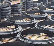
Stainless Steel DIN 2502 PN16 Flange
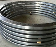
DIN 2502 PN16 Plate Flange
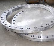
DIN 2502 16 Form c Flange
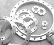
Carbon steel DIN 2502 PN16 Flange
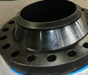
DIN Alloy Steel 2502 Flange
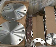
DIN 2502 PN16 Blind Flange
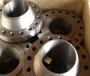
DIN 2502 PN16 Slip On Flange
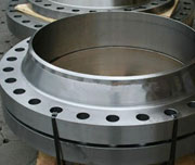
DIN 2502 16 Form C Flange Material
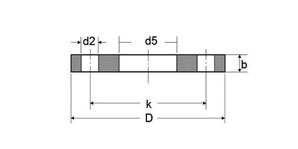
| NPS | Diam. of | Flanges Diameter | Flanges I.D | Thickness of Flanges | Diameter of Bolt Cirlce | Number of | Diameter of Bolt Holes | Weight |
|---|---|---|---|---|---|---|---|---|
| DN | Pipe | D | D5 | B | K | holes | D2 | Kilogram |
| 10 | 17.20 | 90 | 17.70 | 14 | 60 | 4 | 14 | 0.60 |
| 15 | 21.30 | 95 | 22.00 | 14 | 65 | 4 | 14 | 0.67 |
| 20 | 26.90 | 105 | 27.60 | 16 | 75 | 4 | 14 | 0.94 |
| 25 | 33.70 | 115 | 34.40 | 16 | 85 | 4 | 14 | 1.11 |
| 32 | 42.40 | 140 | 43.10 | 16 | 100 | 4 | 18 | 1.62 |
| 40 | 48.30 | 150 | 49.00 | 16 | 110 | 4 | 18 | 1.85 |
| 50 | 60.30 | 165 | 61.10 | 18 | 125 | 4 | 18 | 2.46 |
| 65 | 76.10 | 185 | 77.10 | 18 | 145 | 4 | 18 | 2.99 |
| 80 | 88.90 | 200 | 90.30 | 20 | 160 | 8 | 18 | 3.61 |
| 100 | 114.30 | 220 | 115.90 | 20 | 180 | 8 | 18 | 3.99 |
| 125 | 139.70 | 250 | 141.60 | 22 | 210 | 8 | 18 | 5.41 |
| 150 | 168.30 | 285 | 170.50 | 22 | 240 | 8 | 22 | 6.55 |
| 175 | 193.70 | 315 | 196.10 | 24 | 270 | 8 | 22 | 8.42 |
| 200 | 219.10 | 340 | 221.80 | 24 | 295 | 12 | 22 | 8.97 |
| 250 | 273.00 | 405 | 276.20 | 26 | 355 | 12 | 26 | 12.76 |
| 300 | 323.90 | 460 | 327.60 | 28 | 410 | 12 | 26 | 16.60 |
| 350 | 355.60 | 520 | 359.70 | 30 | 470 | 16 | 26 | 24.08 |
| 400 | 406.40 | 580 | 411.00 | 32 | 525 | 16 | 30 | 30.20 |
| 450 | 457.00 | 640 | 462.30 | 38 | 585 | 20 | 30 | 41.67 |
| 500 | 508.00 | 715 | 513.60 | 38 | 650 | 20 | 33 | 52.87 |
| 600 | 610.00 | 840 | 616.50 | 42 | 770 | 20 | 36 | 77.58 |
| 700 | 711.00 | 910 | 716.00 | 44 | 840 | 24 | 36 | 77.13 |
| 800 | 813.00 | 1025 | 818.00 | 50 | 950 | 24 | 39 | 106.35 |
| 900 | 914.00 | 1125 | 920.00 | 54 | 1050 | 28 | 39 | 125.39 |
| 1000 | 1016.00 | 1255 | 1022.00 | 60 | 1170 | 28 | 42 | 177.99 |
| Temperature (in F°) | Class 150 | Class 300 | Class 400 | Class 600 | Class 900 | Class 1500 | Class 2500 |
| < 100 | 285 | 740 | 985 | 1480 | 2220 | 3705 | 6170 |
| 200 | 260 | 680 | 905 | 1360 | 2035 | 3395 | 5655 |
| 300 | 230 | 655 | 870 | 1310 | 1965 | 3270 | 5450 |
| 400 | 200 | 635 | 845 | 1265 | 1900 | 3170 | 5280 |
| 500 | 170 | 605 | 805 | 1205 | 1810 | 3015 | 5025 |
| 600 | 140 | 570 | 755 | 1135 | 1705 | 2840 | 4730 |
| 650 | 125 | 550 | 730 | 1100 | 1650 | 2745 | 4575 |
| 700 | 110 | 530 | 710 | 1060 | 1590 | 2655 | 4425 |
| 750 | 95 | 505 | 675 | 1015 | 1520 | 2535 | 4230 |
| 800 | 80 | 410 | 550 | 825 | 1235 | 2055 | 3430 |
| 850 | 65 | 320 | 425 | 640 | 955 | 1595 | 2655 |
| 900 | 50 | 230 | 305 | 460 | 690 | 1150 | 1915 |
| 950 | 35 | 135 | 185 | 275 | 410 | 685 | 1145 |
| 1000 | 20 | 85 | 115 | 170 | 255 | 430 | 715 |
| Hydrostatic Test (psig) | 450 | 1125 | 1500 | 2225 | 3350 | 5575 | 9275 |
| NPS NPS (inch) |
|||||
|---|---|---|---|---|---|
| Diammeter of Flange (inch) |
No. of Bolts |
Diammeter of Bolts (inch) |
Diammeter of Bolt Holes (inch) |
Bolt Circle (inch) |
|
| 1/4 | 3-3/8 | 4 | 1/2 | 0.62 | 2-1/4 |
| 1/2 | 3-1/2 | 4 | 1/2 | 0.62 | 2-3/8 |
| 3/4 | 3-7/8 | 4 | 1/2 | 0.62 | 2-3/4 |
| 1 | 4-1/4 | 4 | 1/2 | 0.62 | 3-1/8 |
| 1-1/4 | 4-5/8 | 4 | 1/2 | 0.62 | 3-1/2 |
| 1-1/2 | 5 | 4 | 1/2 | 0.62 | 3-7/8 |
| 2 | 6 | 4 | 5/8 | 0.75 | 4-3/4 |
| 2-1/2 | 7 | 4 | 5/8 | 0.75 | 5-1/2 |
| 3 | 7-1/2 | 4 | 5/8 | 0.75 | 6 |
| 3-1/2 | 8-1/2 | 8 | 5/8 | 0.75 | 7 |
| 4 | 9 | 8 | 5/8 | 0.75 | 7-1/2 |
| 5 | 10 | 8 | 3/4 | 0.88 | 8-1/2 |
| 6 | 11 | 8 | 3/4 | 0.88 | 9-1/2 |
| 8 | 13-1/2 | 8 | 3/4 | 0.88 | 11-3/4 |
| 10 | 16 | 12 | 7/8 | 1 | 14-1/4 |
| 12 | 19 | 12 | 7/8 | 1 | 17 |
| 14 | 21 | 12 | 1 | 1.12 | 18-3/4 |
| 16 | 23-1/2 | 16 | 1 | 1.12 | 21-1/4 |
| 18 | 25 | 16 | 1-1/8 | 1.25 | 22-3/4 |
| 20 | 27-1/2 | 20 | 1-1/8 | 1.25 | 25 |
| 24 | 32 | 20 | 1-1/4 | 1.38 | 29-1/2 |