-
call us
022 23857766 \ 022 67437326 -
send us mail
sales@globalstainless.co.in
| Specification : | ASME B16.47 Series B Flange |
| Coating Flanges Faces : | Anti-rust Paint, Zinc Plated, Oil Black Paint, Yellow Transparent, Cold and Hot Dip Galvanized |
| Production Process: | Forged, Heat Treated and Machined |
| Connect Type Type: | LJF, LMF, RTJ, SMF, RF, FF |
| Size Chart : | 1/2″ (15 NB) To 48″ (1200NB) |
| Application: | Chemical Industry Water Pipeline Industry Natural Gas Industry Oil And Gas Industry Nuclear Power Plant Fabrication Industry |
| Machining Equipment: | Press machine, Pushing Machine, Electric bevelling machine, Bending machine, Sand-blasting machine etc |
| Standards : | ASME B16.47 (Series A, Series B) Flange, PN Flange, ISO Flange, BS10 Flange, JIS Flange, MSS SP44 Flange, EN-1092 Flange, ASME B16.38 Flange, UNI Flange, ASME B16.5 Flange, AWWA Flange, DIN Flange, GOST Flange |
| Design For Size: | ASA, PN, JIS, ANSI, ASME, EN, DIN, BS |
| Pressure Rating Table: | Class 150 LBS, Class 300 LBS, Class 600 LBS, Class 900 LBS, Class 1500 LBS, Class 2500 LBS |
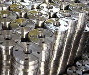
Dn400 300# RF ASME ASME B16.47 Series B 300 Lb Flange
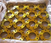
Forged Flange UNS S32205 B16.47 Seriess B Blind Flange
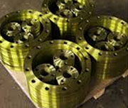
AS 4087 F316L DN65 PN16 ASME B16.47 Series B And Seriess B Flange
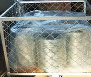
600LBS A105 ASME B16.47 Seriess B Rtj Flange
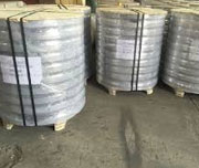
150# ASTM A105 ASME B16.47 Seriess B Blind Flange
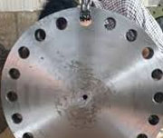
Class 600 WN RF ASME B16.47 Seriess B Slip On Flange
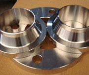
Gost Cs Ct20 Forged Seriess B 150 Lb Flange
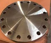
150LBS 12 Inch Lapped ASME 16.47 Seriess B Flange
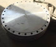
Din 2501 Pn10 A105 Stainless Steel Flange B16.47 Seriess B
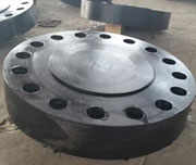
ASME b16.5 Class 150 RF ANSI B16 47 Seriess B (Mss Sp-44) Flange
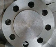
Forged WN Carbon Steel B16.47 Seriess B Reducing Flange
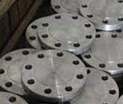
WN FF STD CS ASTM A105n ANSI B16.47 Seriess B Rtj Flange
| NPS | OD (OD) | Minimum Thickness [Note1] – Weld Neck (tf) | Outside Diameter Thickness [Note1] – Blind (tf) | Length Through Hub (Y) | Hub Diameter Base [Note2] (X) | Hub Diameter Top (A) | Raised Face Diameter (R) | Drilling – Bolt Circle Diameter | Drilling – Number of Bolt Holes | Drilling – Diameter of Bolt Hole | Diameter of Bolt | Minimum Fillet Radius (r1) |
|---|---|---|---|---|---|---|---|---|---|---|---|---|
| 26 | 30.00 | 1.25 | 1.25 | 2.25 | 26.62 | 26.06 | 27.75 | 28.50 | 36 | 3⁄4 | 5⁄8 | 0.31 |
| 28 | 32.00 | 1.25 | 1.25 | 2.38 | 28.62 | 28.06 | 29.75 | 30.50 | 40 | 3⁄4 | 5⁄8 | 0.31 |
| 30 | 34.00 | 1.25 | 1.25 | 2.50 | 30.62 | 30.06 | 31.75 | 32.50 | 44 | 34 | 58 | 0.31 |
| 32 | 36.00 | 1.32 | 1.38 | 2.69 | 32.62 | 32.06 | 33.75 | 34.50 | 48 | 34 | 58 | 0.31 |
| 34 | 38.00 | 1.32 | 1.44 | 2.82 | 34.62 | 34.06 | 35.75 | 36.50 | 52 | 34 | 58 | 0.31 |
| 36 | 40.69 | 1.38 | 1.61 | 3.32 | 36.81 | 36.06 | 38.00 | 39.06 | 40 | 78 | 34 | 0.38 |
| 38 | 42.69 | 1.44 | 1.69 | 3.44 | 38.81 | 38.06 | 40.00 | 41.06 | 40 | 78 | 34 | 0.38 |
| 40 | 44.69 | 1.44 | 1.69 | 3.57 | 40.81 | 40.06 | 42.00 | 43.06 | 44 | 78 | 34 | 0.38 |
| 42 | 46.69 | 1.50 | 1.82 | 3.69 | 42.81 | 42.06 | 44.00 | 45.06 | 48 | 78 | 34 | 0.38 |
| 44 | 49.25 | 1.63 | 1.88 | 4.07 | 44.88 | 44.06 | 46.25 | 47.38 | 36 | 1 | 78 | 0.38 |
| 46 | 51.25 | 1.69 | 1.94 | 4.19 | 46.88 | 46.06 | 48.25 | 49.38 | 40 | 1 | 78 | 0.38 |
| 48 | 53.25 | 1.75 | 2.07 | 4.32 | 48.88 | 48.06 | 50.25 | 51.38 | 44 | 1 | 78 | 0.38 |
| 50 | 55.25 | 1.82 | 2.13 | 4.50 | 50.94 | 50.06 | 52.25 | 53.38 | 44 | 1 | 78 | 0.38 |
| 52 | 57.38 | 1.82 | 2.19 | 4.69 | 52.94 | 52.06 | 54.25 | 55.50 | 48 | 1 | 78 | 0.38 |
| 54 | 59.38 | 1.88 | 2.32 | 4.88 | 55.00 | 54.06 | 56.25 | 57.50 | 48 | 1 | 78 | 0.38 |
| 56 | 62.00 | 1.94 | 2.38 | 5.25 | 57.12 | 56.06 | 58.50 | 59.88 | 40 | 118 | 1 | 0.44 |
| 58 | 64.00 | 2.00 | 2.44 | 5.38 | 59.12 | 58.06 | 60.50 | 61.88 | 44 | 118 | 1 | 0.44 |
| 60 | 66.00 | 2.13 | 2.57 | 5.63 | 61.12 | 60.06 | 62.50 | 63.88 | 44 | 118 | 1 | 0.44 |
| NPS | OD
(Outside Diameter |
Minimum Thickness [Note1] – Weld Neck
(tf) |
Minimum Thickness [Note1] – Blind
(tf) |
Length Through Hub
(Y) |
Hub Diameter Base [Note2]
(X) |
Hub Diameter Top
(A) |
Raised Face Diameter
(R) |
Drilling – Bolt Circle Diameter | Drilling – Number of Bolt Holes | Drilling – Diameter of Bolt Hole | Diameter of Bolt | Minimum Fillet Radius
(r1) |
|---|---|---|---|---|---|---|---|---|---|---|---|---|
| 26 | 30.94 | 1.57 | 1.69 | 3.44 | 26.94 | 26.06 | 28.00 | 29.31 | 36 | 7\8 | 3\4 | 0.38 |
| 28 | 32.94 | 1.69 | 1.82 | 3.69 | 28.94 | 28.06 | 30.00 | 31.31 | 40 | 78 | 34 | 0.38 |
| 30 | 34.94 | 1.69 | 1.94 | 3.88 | 31.00 | 30.06 | 32.00 | 33.31 | 44 | 78 | 34 | 0.38 |
| 32 | 37.06 | 1.75 | 2.07 | 4.19 | 33.06 | 32.06 | 34.00 | 35.44 | 48 | 78 | 34 | 0.38 |
| 34 | 39.56 | 1.88 | 2.19 | 4.28 | 35.12 | 34.06 | 36.25 | 37.69 | 40 | 1 | 78 | 0.38 |
| 36 | 41.62 | 2.00 | 2.25 | 4.57 | 37.19 | 36.06 | 38.25 | 39.75 | 44 | 1 | 78 | 0.38 |
| 38 | 44.25 | 2.07 | 2.44 | 4.82 | 39.25 | 38.12 | 40.25 | 42.12 | 40 | 118 | 1 | 0.38 |
| 40 | 46.25 | 2.13 | 2.57 | 5.00 | 41.31 | 40.12 | 42.50 | 44.12 | 44 | 118 | 1 | 0.38 |
| 42 | 48.25 | 2.25 | 2.63 | 5.19 | 43.38 | 42.12 | 44.50 | 46.12 | 48 | 118 | 1 | 0.44 |
| 44 | 50.25 | 2.32 | 2.75 | 5.32 | 45.38 | 44.12 | 46.50 | 48.12 | 52 | 118 | 1 | 0.44 |
| 46 | 52.81 | 2.38 | 2.88 | 5.63 | 47.44 | 46.12 | 48.62 | 50.56 | 40 | 114 | 118 | 0.44 |
| 48 | 54.81 | 2.50 | 3.00 | 5.82 | 48.50 | 48.12 | 50.75 | 52.56 | 44 | 114 | 118 | 0.44 |
| 50 | 56.81 | 2.63 | 3.13 | 6.00 | 51.50 | 50.12 | 52.75 | 54.56 | 48 | 114 | 118 | 0.44 |
| 52 | 58.81 | 2.69 | 3.25 | 6.13 | 53.56 | 52.12 | 54.75 | 56.56 | 52 | 114 | 118 | 0.44 |
| 54 | 61.00 | 2.75 | 3.38 | 6.32 | 55.62 | 54.12 | 56.75 | 58.75 | 56 | 114 | 118 | 0.44 |
| 56 | 63.00 | 2.82 | 3.50 | 6.50 | 57.69 | 56.12 | 58.75 | 60.75 | 60 | 114 | 118 | 0.56 |
| 58 | 65.94 | 2.88 | 3.62 | 6.82 | 59.69 | 58.12 | 60.75 | 63.44 | 48 | 138 | 114 | 0.56 |
| 60 | 67.94 | 2.94 | 3.75 | 7.00 | 61.81 | 60.12 | 63.00 | 65.44 | 52 | 138 | 114 | 0.56 |
| NPS | OD
(Outside Diameter |
Minimum Thickness [Note1] – Weld Neck
(tf) |
Minimum Thickness [Note1] – Blind
(tf) |
Length Through Hub
(Y) |
Hub Diameter Base [Note2]
(X) |
Hub Diameter Top
(A) |
Raised Face Diameter
(R) |
Drilling – Bolt Circle Diameter | Drilling – Number of Bolt Holes | Drilling – Diameter of Bolt Hole | Diameter of Bolt | Minimum Fillet Radius
(r1) |
|---|---|---|---|---|---|---|---|---|---|---|---|---|
| 26 | 34.12 | 3.44 | 3.44 | 5.63 | 27.62 | 26.19 | 29.00 | 31.62 | 32 | 138 | 114 | 0.56 |
| 28 | 36.25 | 3.44 | 3.44 | 5.81 | 29.75 | 28.19 | 31.00 | 33.75 | 36 | 138 | 114 | 0.56 |
| 30 | 39.00 | 3.63 | 3.63 | 6.16 | 32.00 | 30.25 | 33.25 | 36.25 | 36 | 112 | 138 | 0.56 |
| 32 | 41.50 | 4.00 | 4.00 | 6.56 | 34.00 | 32.35 | 35.50 | 38.50 | 32 | 158 | 112 | 0.62 |
| 34 | 43.62 | 4.00 | 4.00 | 6.75 | 36.12 | 34.25 | 37.50 | 40.62 | 36 | 158 | 112 | 0.62 |
| 36 | 46.12 | 4.00 | 4.00 | 7.06 | 38.00 | 36.25 | 39.75 | 42.88 | 32 | 134 | 158 | 0.62 |
| 38 | 48.12 | 4.31 | 4.31 | 7.50 | 40.00 | 38.25 | 41.75 | 44.88 | 36 | 134 | 158 | 0.62 |
| 40 | 50.12 | 4.50 | 4.50 | 7.75 | 42.00 | 40.25 | 43.88 | 46.88 | 40 | 13\4 | 15\8 | 0.62 |
| 42 | 52.50 | 4.63 | 4.63 | 8.00 | 44.00 | 42.31 | 46.00 | 49.00 | 36 | 17\8 | 13\4 | 0.62 |
| 44 | 54.50 | 4.94 | 4.94 | 8.38 | 46.19 | 44.31 | 48.00 | 51.00 | 40 | 17\8 | 13\4 | 0.62 |
| 46 | 57.50 | 5.00 | 5.06 | 8.69 | 48.38 | 46.31 | 50.00 | 53.75 | 36 | 2 | 17\8 | 0.62 |
| 48 | 59.50 | 5.00 | 5.25 | 8.75 | 50.31 | 48.31 | 52.25 | 55.75 | 40 | 2 | 17\8 | 0.62 |
| 50 | 61.50 | 5.38 | 5.44 | 9.19 | 52.38 | 50.31 | 54.25 | 57.75 | 44 | 2 | 17\8 | 0.62 |
| 52 | 63.50 | 5.56 | 5.61 | 9.50 | 54.44 | 52.31 | 56.25 | 59.75 | 48 | 2 | 17\8 | 0.62 |
| 54 | 65.88 | 5.32 | 5.81 | 9.38 | 56.50 | 54.31 | 58.25 | 62.12 | 48 | 2 | 17\8 | 0.62 |
| 56 | 69.50 | 6.00 | 6.12 | 10.50 | 58.81 | 56.31 | 60.50 | 65.00 | 36 | 23\8 | 21\4 | 0.69 |
| 58 | 71.94 | 6.00 | 6.31 | 10.75 | 60.94 | 58.31 | 62.75 | 67.44 | 40 | 23\8 | 21\4 | 0.69 |
| 60 | 73.94 | 5.88 | 6.50 | 10.63 | 62.94 | 60.31 | 65.00 | 69.44 | 40 | 23\8 | 21\4 | 0.69 |
| NPS | OD
(Outside Diameter |
Minimum Thickness [Note1] – Weld Neck
(tf) |
Minimum Thickness [Note1] – Blind
(tf) |
Length Through Hub
(Y) |
Hub Diameter Base [Note2]
(X) |
Hub Diameter Top
(A) |
Raised Face Diameter
(R) |
Drilling – Bolt Circle Diameter | Drilling – Number of Bolt Holes | Drilling – Diameter of Bolt Hole | Diameter of Bolt | Minimum Fillet Radius
(r1) |
|---|---|---|---|---|---|---|---|---|---|---|---|---|
| 26 | 35.00 | 4.38 | 4.38 | 7.12 | 27.50 | 26.00 | 28.62 | 31.75 | 28 | 13\4 | 15\8 | 0.50 |
| 28 | 37.50 | 4.56 | 4.56 | 7.50 | 29.62 | 28.00 | 30.88 | 34.00 | 28 | 17\8 | 13\4 | 0.50 |
| 30 | 40.25 | 4.94 | 5.00 | 8.06 | 31.75 | 30.00 | 33.12 | 36.50 | 28 | 2 | 17\8 | 0.50 |
| 32 | 42.75 | 5.12 | 5.31 | 8.50 | 33.88 | 32.00 | 35.25 | 38.75 | 28 | 21\8 | 2 | 0.50 |
| 34 | 45.75 | 5.56 | 5.68 | 9.19 | 36.00 | 34.00 | 37.50 | 41.50 | 24 | 23\8 | 21\4 | 0.56 |
| 36 | 47.75 | 5.75 | 5.94 | 9.56 | 38.12 | 36.00 | 39.75 | 43.50 | 28 | 23\8 | 21\4 | 0.56 |
| 38 | 50.00 | 6.00 | 6.12 | 10.00 | 40.25 | 38.00 | 41.50 | 45.75 | 28 | 23\8 | 21\4 | 0.56 |
| 40 | 52.00 | 6.25 | 6.38 | 10.38 | 42.25 | 40.00 | 43.75 | 47.75 | 32 | 23\8 | 21\4 | 0.56 |
| 42 | 55.25 | 6.62 | 6.75 | 11.00 | 44.38 | 42.00 | 46.00 | 50.50 | 28 | 25\8 | 21\2 | 0.56 |
| 44 | 57.25 | 6.81 | 7.00 | 11.38 | 46.50 | 44.00 | 48.25 | 52.50 | 32 | 25\8 | 21\2 | 0.56 |
| 46 | 59.50 | 7.06 | 7.31 | 11.81 | 48.62 | 46.00 | 50.25 | 54.75 | 32 | 25\8 | 21\2 | 0.56 |
| 48 | 62.75 | 7.44 | 7.69 | 12.44 | 50.75 | 48.00 | 52.25 | 57.50 | 32 | 27\8 | 23\4 | 0.56 |
| 50 | 65.75 | 7.75 | 8.00 | 12.94 | 52.88 | 50.00 | 54.50 | 60.00 | 28 | 31\8 | 3 | 0.56 |
| 52 | 67.75 | 8.00 | 8.25 | 13.25 | 54.88 | 52.00 | 56.50 | 62.00 | 32 | 31\8 | 3 | 0.56 |
| 54 | 70.00 | 8.25 | 8.56 | 13.75 | 57.00 | 54.00 | 58.75 | 64.25 | 32 | 31\8 | 3 | 0.56 |
| 56 | 73.00 | 8.56 | 8.88 | 14.25 | 59.12 | 56.00 | 60.75 | 66.75 | 32 | 33\8 | 31\4 | 0.62 |
| 58 | 75.00 | 8.75 | 9.12 | 14.56 | 61.12 | 58.00 | 63.00 | 68.75 | 32 | 33\8 | 31\4 | 0.62 |
| 60 | 78.50 | 9.19 | 9.56 | 15.31 | 63.38 | 60.00 | 65.25 | 71.75 | 28 | 35\8 | 31\2 | 0.69 |
| NPS | OD
(Outside Diameter |
Minimum Thickness [Note1] – Weld Neck
(tf) |
Minimum Thickness [Note1] – Blind
(tf) |
Length Through Hub
(Y) |
Hub Diameter Base [Note2]
(X) |
Hub Diameter Top
(A) |
Raised Face Diameter
(R) |
Drilling – Bolt Circle Diameter | Drilling – Number of Bolt Holes | Drilling – Diameter of Bolt Hole | Diameter of Bolt | Minimum Fillet Radius
(r1) |
|---|---|---|---|---|---|---|---|---|---|---|---|---|
| 26 | 40.25 | 5.31 | 6.06 | 10.19 | 29.25 | 26.00 | 30.00 | 35.50 | 20 | 25\8 | 21\2 | 0.44 |
| 28 | 43.50 | 5.81 | 6.56 | 10.88 | 31.38 | 28.00 | 32.25 | 38.25 | 20 | 27\8 | 23\4 | 0.50 |
| 30 | 46.50 | 6.12 | 6.93 | 11.38 | 33.50 | 30.00 | 34.50 | 40.75 | 20 | 31\8 | 3 | 0.50 |
| 32 | 48.75 | 6.31 | 7.31 | 11.94 | 35.75 | 32.00 | 36.50 | 43.00 | 20 | 31\8 | 3 | 0.50 |
| 34 | 51.75 | 6.75 | 7.68 | 12.56 | 37.88 | 34.00 | 39.00 | 45.50 | 20 | 33\8 | 31\4 | 0.56 |
| 36 | 53.00 | 6.81 | 7.94 | 12.81 | 40.00 | 36.00 | 40.50 | 47.25 | 24 | 31\8 | 3 | 0.56 |
| 38 | 57.50 | 7.50 | 8.50 | 13.88 | 42.25 | 38.00 | 43.25 | 50.75 | 20 | 35\8 | 31\2 | 0.75 |
| 40 | 59.50 | 7.75 | 8.81 | 14.31 | 44.38 | 40.00 | 45.75 | 52.75 | 24 | 35\8 | 31\2 | 0.81 |
| 42 | 61.50 | 8.12 | 9.12 | 14.62 | 46.31 | 42.00 | 47.75 | 54.75 | 24 | 35\8 | 31\2 | 0.81 |
| 44 | 64.88 | 8.44 | 9.56 | 15.38 | 48.62 | 44.00 | 50.00 | 57.62 | 24 | 37\8 | 33\4 | 0.88 |
| 46 | 68.25 | 8.88 | 10.06 | 16.18 | 50.88 | 46.00 | 52.50 | 60.50 | 24 | 41\8 | 4 | 0.88 |
| 48 | 70.25 | 9.19 | 10.38 | 16.50 | 52.88 | 48.00 | 54.50 | 62.50 | 24 | 41\8 | 4 | 0.94 |
| Normal Pipe Size | Dimensions | Weight (Kilogram) | ||||
|---|---|---|---|---|---|---|
| NPS (In.) |
DN (millimeter) | FLANGE Outer Diameter Millimeter Millimeter |
FLANGE Thickness D millimeter |
SOW Socket Weld |
Weld Neck | Blind |
| 1/2 | 15 | 88.9 | 11.2 | 0.4 | 0.5 | 0.4 |
| 3/4 | 20 | 98.6 | 12.7 | 0.6 | 0.7 | 0.6 |
| 1 | 25 | 108 | 14.2 | 0.8 | 1 | 0.9 |
| 1 1/4 | 32 | 117.3 | 15.7 | 1 | 1.3 | 1.2 |
| 1 1/2 | 40 | 127 | 17.5 | 1.3 | 1.7 | 1.5 |
| 2 | 50 | 152.4 | 19.1 | 2.1 | 2.6 | 2.4 |
| 2 1/2 | 65 | 177.8 | 22.4 | 3.3 | 4.1 | 3.9 |
| 3 | 80 | 190.5 | 23.9 | 3.9 | 4.9 | 4.9 |
| 3 1/2 | 90 | 215.9 | 23.9 | 4.8 | 6.1 | 6.2 |
| 4 | 100 | 228.6 | 23.9 | 5.3 | 6.8 | 7.0 |
| 5 | 125 | 254 | 23.9 | 6.1 | 8.6 | 8.6 |
| 6 | 150 | 279.4 | 25.4 | 7.5 | 10.6 | 11.3 |
| 8 | 200 | 342.9 | 28.4 | 12.1 | 17.6 | 19.6 |
| 10 | 250 | 406.4 | 30.2 | 16.5 | 24 | 28.6 |
| 12 | 300 | 482.6 | 31.8 | 26.2 | 36.5 | 43.2 |
| 14 | 350 | 533.4 | 35.1 | 34.6 | 48.4 | 58.1 |
| 16 | 400 | 596.9 | 36.6 | 44.8 | 60.6 | 76.1 |
| 18 | 450 | 635 | 39.6 | 48.9 | 68.3 | 93.7 |
| 20 | 500 | 698.5 | 42.9 | 61.9 | 84.5 | 122.0 |
| 24 | 600 | 812.8 | 47.8 | 86.9 | 115 | 185.0 |
|
Temperature |
||||||||
|
Flange Tables |
-10° |
250° |
300° |
350° |
400° |
425° |
450° |
475° |
|
6 |
6 |
5.5 |
5 |
– |
– |
– |
– |
– |
|
10 |
10 |
9 |
8 |
7 |
6 |
– |
– |
– |
|
16 |
16 |
15 |
13 |
11 |
9 |
– |
– |
– |
|
25 |
25 |
24 |
21 |
17 |
14 |
12 |
9 |
6 |
|
40 |
40 |
38 |
33 |
28 |
23 |
20 |
15 |
10 |
|
64 |
64 |
61 |
53 |
44 |
36 |
32 |
24 |
16 |
|
100 |
100 |
95 |
83 |
70 |
57 |
50 |
37 |
25 |
|
160 |
160 |
152 |
132 |
112 |
92 |
80 |
60 |
40 |