-
call us
022 23857766 \ 022 67437326 -
send us mail
sales@globalstainless.co.in
| Specification : | ASME B16.47 Series A Flange |
| Standards : | ASME B16.47 (Series A, Series B) Flange, PN Flange, ISO Flange, BS10 Flange, JIS Flange, MSS SP44 Flange, EN-1092 Flange, ASME B16.38 Flange, UNI Flange, ASME B16.5 Flange, AWWA Flange, DIN Flange, GOST Flange |
| Design For Size: | ASA, PN, JIS, ANSI, ASME, EN, DIN, BS |
| Pressure Rating Table: | Class 150 LBS, Class 300 LBS, Class 600 LBS, Class 900 LBS, Class 1500 LBS, Class 2500 LBS |
| Application: | Chemical Industry Oil And Gas Industry Natural Gas Industry Nuclear Power Plant Water Pipeline Industry Fabrication Industry |
| Connect Type Type: | SMF, RF, FF, LJF, LMF, RTJ. |
| Size Chart : | 1/2″ (15 NB) To 48″ (1200NB) |
| Coating Flange Faces : | Zinc Plated, Oil Black Paint, Anti-rust Paint, Yellow Transparent, Cold and Hot Dip Galvanized |
| Production Process: | Forged, Heat Treated and Machined |
| Machining Equipment: | Electric bevelling machine, Press machine, Pushing Machine, Bending machine, Sand-blasting machine etc |
|
Temperature Table |
||||||||
|
Tables Of Flanges |
Celsius -10° |
Celsius 250° |
Celsius 300° |
Celsius 350° |
Celsius 400° |
Celsius 425° |
Celsius 450° |
Celsius 475° |
|
6 |
6 |
5.5 |
5 |
– |
– |
– |
– |
– |
|
10 |
10 |
9 |
8 |
7 |
6 |
– |
– |
– |
|
16 |
16 |
15 |
13 |
11 |
9 |
– |
– |
– |
|
25 |
25 |
24 |
21 |
17 |
14 |
12 |
9 |
6 |
|
40 |
40 |
38 |
33 |
28 |
23 |
20 |
15 |
10 |
|
64 |
64 |
61 |
53 |
44 |
36 |
32 |
24 |
16 |
|
100 |
100 |
95 |
83 |
70 |
57 |
50 |
37 |
25 |
|
160 |
160 |
152 |
132 |
112 |
92 |
80 |
60 |
40 |
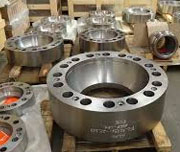
Din 2501 Pn10 A105 Stainless Steel Flange B16.47 Series A
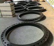
ASME b16.5 Class 150 RF ANSI B16 47 Series A (Mss Sp-44) Flange
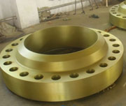
Forged WN Carbon Steel B16.47 Series A Reducing Flange
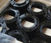
WN FF STD CS ASTM A105n ANSI B16.47 Series A Rtj Flange
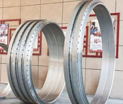
Dn400 300# RF ASME ASME B16.47 Series A 300 Lb Flange
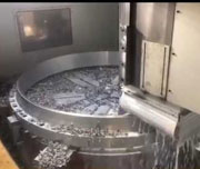
Forged Flange UNS S32205 B16.47 Series A Blind Flange
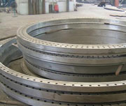
AS 4087 F316L DN65 PN16 ASME B16.47 Series A And Series B Flange
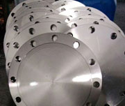
600LBS A105 ASME B16.47 Series A Rtj Flange
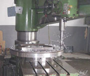
150# ASTM A105 ASME B16.47 Series A Blind Flange
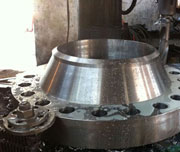
Class 600 WN RF ASME B16.47 Series A Slip On Flange
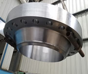
Gost Cs Ct20 Forged Series A 150 Lb Flange
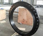
150LBS 12 Inch Lapped ASME 16.47 Series B Flange
| Normal Pipe Sizes | (O.D.) | Thickness Of Weld Neck (minimum)
(tf) |
Thickness Of Blind (minimum)
(tf) |
Hub (Y) Length Through | Diameter Base Of Hub
(X) |
Diameter Of Top Hub
(A) |
Diameter Of Raised Face
(R) |
Drilling – Diameter Of Bolt Circle | Drilling – Number of Bolts Holes | Drilling – Bolts Holes Diameter | Bolts Diameters | Fillet Radius (minimum)
(r1) |
|---|---|---|---|---|---|---|---|---|---|---|---|---|
| 26 | 34.25 | 2.63 | 2.63 | 4.69 | 26.62 | 26.00 | 29.50 | 31.75 | 24 | 138 | 114 | 0.38 |
| 28 | 36.50 | 2.75 | 2.75 | 4.88 | 28.62 | 28.00 | 31.50 | 34.00 | 28 | 138 | 114 | 0.44 |
| 30 | 38.75 | 2.88 | 2.88 | 5.32 | 30.75 | 30.00 | 33.75 | 36.00 | 28 | 138 | 114 | 0.44 |
| 32 | 41.75 | 3.13 | 3.13 | 5.63 | 32.75 | 32.00 | 36.00 | 38.50 | 28 | 158 | 112 | 0.44 |
| 34 | 43.75 | 3.19 | 3.19 | 5.82 | 34.75 | 34.00 | 38.00 | 40.50 | 32 | 158 | 112 | 0.50 |
| 36 | 46.00 | 3.50 | 3.50 | 6.13 | 36.75 | 36.00 | 40.25 | 42.75 | 32 | 158 | 112 | 0.50 |
| 38 | 48.75 | 3.38 | 3.38 | 6.13 | 39.00 | 38.00 | 42.25 | 45.25 | 32 | 158 | 112 | 0.50 |
| 40 | 50.75 | 3.50 | 3.50 | 6.38 | 41.00 | 40.00 | 44.25 | 47.25 | 36 | 158 | 112 | 0.50 |
| 42 | 53.00 | 3.75 | 3.75 | 6.69 | 43.00 | 42.00 | 47.00 | 49.50 | 36 | 158 | 112 | 0.50 |
| 44 | 55.25 | 3.94 | 3.94 | 6.94 | 45.00 | 44.00 | 49.00 | 51.75 | 40 | 158 | 112 | 0.50 |
| 46 | 57.25 | 4.00 | 4.00 | 7.25 | 47.12 | 46.00 | 51.00 | 53.75 | 40 | 158 | 112 | 0.50 |
| 48 | 59.50 | 4.19 | 4.19 | 7.50 | 49.12 | 48.00 | 53.50 | 56.00 | 44 | 158 | 112 | 0.50 |
| 50 | 61.75 | 4.32 | 4.32 | 7.94 | 51.25 | 50.00 | 55.50 | 58.25 | 44 | 178 | 134 | 0.50 |
| 52 | 64.00 | 4.50 | 4.50 | 8.19 | 53.25 | 52.00 | 57.50 | 60.50 | 44 | 178 | 134 | 0.50 |
| 54 | 66.25 | 4.69 | 4.69 | 8.44 | 55.25 | 54.00 | 59.50 | 62.75 | 44 | 178 | 134 | 0.50 |
| 56 | 68.75 | 4.82 | 4.82 | 8.94 | 57.38 | 56.00 | 62.00 | 65.00 | 48 | 178 | 134 | 0.50 |
| 58 | 71.00 | 5.00 | 5.00 | 9.19 | 59.38 | 58.00 | 64.00 | 67.25 | 48 | 178 | 134 | 0.50 |
| 60 | 73.00 | 5.13 | 5.13 | 9.38 | 61.38 | 60.00 | 66.00 | 69.25 | 52 | 178 | 134 | 0.50 |
| Normal Pipe Sizes | (O.D.) | Thickness Of Weld Neck (minimum)
(tf) |
Thickness Of Blind (minimum)
(tf) |
Hub (Y) Length Through | Diameter Base Of Hub
(X) |
Diameter Of Hub Top
(A) |
Diameter Of Raised Face
(RF) |
Drilling – Diameter Of Bolt Circle | Drilling – Number of Bolts Holes | Drilling – Bolts Holes Diameter | Bolts Diameters | Fillet Radius (minimum)
(r1) |
|---|---|---|---|---|---|---|---|---|---|---|---|---|
| 26 | 38.25 | 3.07 | 3.25 | 7.19 | 28.38 | 26.00 | 29.50 | 34.50 | 28 | 13⁄4 | 15⁄8 | 0.38 |
| 28 | 40.75 | 3.32 | 3.50 | 7.69 | 30.50 | 28.00 | 31.50 | 37.00 | 28 | 13⁄4 | 15⁄8 | 0.44 |
| 30 | 43.00 | 3.57 | 3.69 | 8.19 | 32.56 | 30.00 | 33.75 | 39.25 | 28 | 17⁄8 | 13⁄4 | 0.44 |
| 32 | 45.25 | 3.82 | 3.88 | 8.69 | 34.69 | 32.00 | 36.00 | 41.50 | 28 | 2 | 17⁄8 | 0.44 |
| 34 | 47.50 | 3.94 | 4.07 | 9.07 | 36.88 | 34.00 | 38.00 | 43.50 | 28 | 2 | 17⁄8 | 0.50 |
| 36 | 50.00 | 4.07 | 4.32 | 9.44 | 39.00 | 36.00 | 40.25 | 46.00 | 32 | 21⁄8 | 2 | 0.50 |
| 38 | 46.00 | 4.19 | 4.19 | 7.06 | 39.12 | 38.00 | 40.50 | 43.00 | 32 | 15⁄8 | 11⁄2 | 0.50 |
| 40 | 48.75 | 4.44 | 4.44 | 7.56 | 41.25 | 40.00 | 42.75 | 45.50 | 32 | 13⁄4 | 15⁄8 | 0.50 |
| 42 | 50.75 | 4.63 | 4.63 | 7.82 | 43.25 | 42.00 | 44.75 | 47.50 | 32 | 13⁄4 | 15⁄8 | 0.50 |
| 44 | 53.25 | 4.82 | 4.82 | 8.06 | 45.25 | 44.00 | 47.00 | 49.75 | 32 | 17⁄8 | 13⁄4 | 0.50 |
| 46 | 55.75 | 5.00 | 5.00 | 8.44 | 47.38 | 46.00 | 49.00 | 52.00 | 28 | 2 | 17⁄8 | 0.50 |
| 48 | 57.75 | 5.19 | 5.19 | 8.75 | 49.38 | 48.00 | 51.25 | 54.00 | 32 | 2 | 17⁄8 | 0.50 |
| 50 | 60.25 | 5.44 | 5.44 | 9.07 | 51.38 | 50.00 | 53.50 | 56.25 | 32 | 21⁄8 | 2 | 0.50 |
| 52 | 62.25 | 5.63 | 5.63 | 9.32 | 53.38 | 52.00 | 55.50 | 58.25 | 32 | 21⁄8 | 2 | 0.50 |
| 54 | 65.25 | 5.94 | 5.94 | 9.88 | 55.50 | 54.00 | 57.75 | 61.00 | 28 | 23⁄8 | 21⁄4 | 0.50 |
| 56 | 67.25 | 6.00 | 6.00 | 10.19 | 57.62 | 56.00 | 59.75 | 63.00 | 28 | 23⁄8 | 21⁄4 | 0.50 |
| 58 | 69.25 | 6.19 | 6.19 | 10.44 | 59.62 | 58.00 | 62.00 | 65.00 | 32 | 23⁄8 | 21⁄4 | 0.50 |
| 60 | 71.25 | 6.38 | 6.38 | 10.69 | 61.62 | 60.00 | 64.00 | 67.00 | 32 | 23⁄8 | 21⁄4 | 0.50 |
| Normal Pipe Sizes | (O.D.) | Thickness Of Weld Neck (minimum) (tf) | Thickness Of Blind (minimum) (tf) | Hub (Y) Length Through | Diameter Of Hub Base (X) | Diameter Of Top Hub (A) | Diameter Of Raised Face (RF) | Drilling – Diameter Of Bolt Circle | Drilling- Number of Bolts Holes | Drilling – Bolts Holes Diameter | Bolts Diameters | Fillet Radius (minimum) (r1) |
|---|---|---|---|---|---|---|---|---|---|---|---|---|
| 26 | 38.25 | 3.50 | 3.88 | 7.62 | 28.62 | 26.00 | 29.50 | 34.50 | 28 | 178 | 134 | 0.44 |
| 28 | 40.75 | 3.75 | 4.12 | 8.12 | 30.81 | 28.00 | 31.50 | 37.00 | 28 | 2 | 178 | 0.50 |
| 30 | 43.00 | 4.00 | 4.38 | 8.62 | 32.94 | 30.00 | 33.75 | 39.25 | 28 | 218 | 2 | 0.50 |
| 32 | 45.25 | 4.25 | 4.56 | 9.12 | 35.00 | 32.00 | 36.00 | 41.50 | 28 | 218 | 2 | 0.50 |
| 34 | 47.50 | 4.38 | 4.81 | 9.50 | 37.19 | 34.00 | 38.00 | 43.50 | 28 | 218 | 2 | 0.56 |
| 36 | 50.00 | 4.50 | 5.06 | 9.88 | 39.38 | 36.00 | 40.25 | 46.00 | 32 | 218 | 2 | 0.56 |
| 38 | 47.50 | 4.88 | 4.88 | 8.12 | 39.50 | 38.00 | 40.75 | 44.00 | 32 | 178 | 134 | 0.56 |
| 40 | 50.00 | 5.12 | 5.12 | 8.50 | 41.50 | 40.00 | 43.00 | 46.25 | 32 | 2 | 178 | 0.56 |
| 42 | 52.00 | 5.25 | 5.25 | 8.81 | 43.62 | 42.00 | 45.00 | 48.25 | 32 | 2 | 178 | 0.56 |
| 44 | 54.50 | 5.50 | 5.50 | 9.18 | 45.62 | 44.00 | 47.25 | 50.50 | 32 | 218 | 2 | 0.56 |
| 46 | 56.75 | 5.75 | 5.75 | 9.62 | 47.75 | 46.00 | 49.50 | 52.75 | 36 | 218 | 2 | 0.56 |
| 48 | 59.50 | 6.00 | 6.00 | 10.12 | 49.88 | 48.00 | 51.50 | 55.25 | 28 | 238 | 214 | 0.56 |
| 50 | 61.75 | 6.19 | 6.25 | 10.56 | 52.00 | 50.00 | 53.62 | 57.50 | 32 | 238 | 214 | 0.56 |
| 52 | 63.75 | 6.38 | 6.44 | 10.88 | 54.00 | 52.00 | 55.62 | 59.50 | 32 | 238 | 214 | 0.56 |
| 54 | 67.00 | 6.69 | 6.75 | 11.38 | 56.12 | 54.00 | 57.88 | 62.25 | 28 | 258 | 212 | 0.56 |
| 56 | 69.00 | 6.88 | 6.94 | 11.75 | 58.25 | 56.00 | 60.12 | 64.25 | 32 | 258 | 212 | 0.56 |
| 58 | 71.00 | 7.00 | 7.12 | 12.06 | 60.25 | 58.00 | 62.12 | 66.25 | 32 | 258 | 212 | 0.56 |
| 60 | 74.25 | 7.31 | 7.44 | 12.56 | 62.38 | 60.00 | 64.38 | 69.00 | 32 | 278 | 234 | 0.56 |
| Normal Pipe Sizes | (O.D.) | Thickness Of – Weld Neck (minimum) (tf) | Thickness Of Blind (minimum) (tf) | Hub (Y) Length Through | Diameter Of Hub Base (X) | Diameter Of Top Hub (A) | Diameter Of Raised Face (RF) | Drilling – Diameter Of Bolts Circles | Drilling – Number of Bolts Holes | Drilling – Bolts Holes Diameters | Bolts Diameters | Fillet Radius (minimum) (r1) |
|---|---|---|---|---|---|---|---|---|---|---|---|---|
| 26 | 40.00 | 4.25 | 4.94 | 8.75 | 29.44 | 26.00 | 29.50 | 36.00 | 28 | 2 | 178 | 0.50 |
| 28 | 42.25 | 4.38 | 5.19 | 9.25 | 31.62 | 28.00 | 31.50 | 38.00 | 28 | 218 | 2 | 0.50 |
| 30 | 44.50 | 4.50 | 5.50 | 9.75 | 33.94 | 30.00 | 33.75 | 40.25 | 28 | 218 | 2 | 0.50 |
| 32 | 47.00 | 4.62 | 5.81 | 10.25 | 36.12 | 32.00 | 36.00 | 42.50 | 28 | 238 | 214 | 0.50 |
| 34 | 49.00 | 4.75 | 6.06 | 10.62 | 38.31 | 34.00 | 38.00 | 44.50 | 28 | 238 | 214 | 0.56 |
| 36 | 51.75 | 4.88 | 6.38 | 11.12 | 40.62 | 36.00 | 40.25 | 47.00 | 28 | 258 | 212 | 0.56 |
| 38 | 50.00 | 6.00 | 6.12 | 10.00 | 40.25 | 38.00 | 41.50 | 45.75 | 28 | 238 | 214 | 0.56 |
| 40 | 52.00 | 6.25 | 6.38 | 10.38 | 42.25 | 40.00 | 43.75 | 47.75 | 32 | 238 | 214 | 0.56 |
| 42 | 55.25 | 6.62 | 6.75 | 11.00 | 44.38 | 42.00 | 46.00 | 50.50 | 28 | 258 | 212 | 0.56 |
| 44 | 57.25 | 6.81 | 7.00 | 11.38 | 46.50 | 44.00 | 48.25 | 52.50 | 32 | 258 | 212 | 0.56 |
| 46 | 59.50 | 7.06 | 7.31 | 11.81 | 48.62 | 46.00 | 50.25 | 54.75 | 32 | 258 | 212 | 0.56 |
| 48 | 62.75 | 7.44 | 7.69 | 12.44 | 50.75 | 48.00 | 52.50 | 57.50 | 32 | 278 | 234 | 0.56 |
| 50 | 65.75 | 7.75 | 8.00 | 12.94 | 52.88 | 50.00 | 54.50 | 60.00 | 28 | 318 | 3 | 0.56 |
| 52 | 67.75 | 8.00 | 8.25 | 13.25 | 54.88 | 52.00 | 56.50 | 62.00 | 32 | 318 | 3 | 0.56 |
| 54 | 70.00 | 8.25 | 8.56 | 13.75 | 57.00 | 54.00 | 58.75 | 64.25 | 32 | 318 | 3 | 0.56 |
| 56 | 73.00 | 8.56 | 8.88 | 14.25 | 59.12 | 56.00 | 60.75 | 66.75 | 32 | 338 | 314 | 0.62 |
| 58 | 75.00 | 8.75 | 9.12 | 14.56 | 61.12 | 58.00 | 63.00 | 68.75 | 32 | 338 | 314 | 0.62 |
| 60 | 78.50 | 9.19 | 9.56 | 15.31 | 63.38 | 60.00 | 65.25 | 71.75 | 28 | 358 | 312 | 0.69 |
| Normal Pipe Sizes | (O.D.) | Thickness Of Weld Neck (minimum) (tf) | Thickness Of Blind (minimum) (tf) | Hub (Y) Length Through | Diameter Of Hub Base (X) | Diameter Of Top Hub (A) | Diameter Of Raised Face (RF) | Drilling – Diameter Of Bolts Circles | Drilling – Number of Bolts Holes | Drilling – Bolts Holes Diameter | Bolts Diameters | Fillet Radius (minimum) (r1) |
|---|---|---|---|---|---|---|---|---|---|---|---|---|
| 26 | 42.75 | 5.50 | 6.31 | 11.25 | 30.50 | 26.00 | 29.50 | 37.50 | 20 | 278 | 234 | 0.44 |
| 28 | 46.00 | 5.62 | 6.75 | 11.75 | 32.75 | 28.00 | 31.50 | 40.25 | 20 | 318 | 3 | 0.50 |
| 30 | 48.50 | 5.88 | 7.18 | 12.25 | 35.00 | 30.00 | 33.75 | 42.75 | 20 | 318 | 3 | 0.50 |
| 32 | 51.75 | 6.25 | 7.62 | 13.00 | 37.25 | 32.00 | 36.00 | 45.50 | 20 | 338 | 314 | 0.50 |
| 34 | 55.00 | 6.50 | 8.06 | 13.75 | 39.62 | 34.00 | 38.00 | 48.25 | 20 | 358 | 312 | 0.56 |
| 36 | 57.50 | 6.75 | 8.44 | 14.25 | 41.88 | 36.00 | 40.25 | 50.75 | 20 | 358 | 312 | 0.56 |
| 38 | 57.50 | 7.50 | 8.50 | 13.88 | 42.25 | 38.00 | 43.25 | 50.75 | 20 | 358 | 312 | 0.75 |
| 40 | 59.50 | 7.75 | 8.81 | 14.31 | 44.38 | 40.00 | 45.75 | 52.75 | 24 | 358 | 312 | 0.81 |
| 42 | 61.50 | 8.12 | 9.12 | 14.62 | 46.31 | 42.00 | 47.75 | 54.75 | 24 | 358 | 312 | 0.81 |
| 44 | 64.88 | 8.44 | 9.56 | 15.38 | 48.62 | 44.00 | 50.00 | 57.62 | 24 | 378 | 334 | 0.88 |
| 46 | 68.25 | 8.88 | 10.06 | 16.18 | 50.88 | 46.00 | 52.50 | 60.50 | 24 | 418 | 4 | 0.88 |
| 48 | 70.25 | 9.19 | 10.38 | 16.50 | 52.88 | 48.00 | 54.50 | 62.50 | 24 | 41⁄8 | 4 | 0.94 |
| NPS | Dimensions | Weight In Kilogram | ||||
|---|---|---|---|---|---|---|
| Normal Pipe Sizes (Inches) |
DN MM (millimeter) | FLANGEs (O.D.) MM MM |
Thickness Of Flanges
D millimeter |
Slip On (SORF) Socket Weld (SWRF) |
Weld Neck (WNRF) | Blind (BLRF) |
| 1/2 | 15 | 88.9 | 11.2 | 0.4 | 0.5 | 0.4 |
| 3/4 | 20 | 98.6 | 12.7 | 0.6 | 0.7 | 0.6 |
| 1 | 25 | 108 | 14.2 | 0.8 | 1 | 0.9 |
| 1 1/4 | 32 | 117.3 | 15.7 | 1 | 1.3 | 1.2 |
| 1 1/2 | 40 | 127 | 17.5 | 1.3 | 1.7 | 1.5 |
| 2 | 50 | 152.4 | 19.1 | 2.1 | 2.6 | 2.4 |
| 2 1/2 | 65 | 177.8 | 22.4 | 3.3 | 4.1 | 3.9 |
| 3 | 80 | 190.5 | 23.9 | 3.9 | 4.9 | 4.9 |
| 3 1/2 | 90 | 215.9 | 23.9 | 4.8 | 6.1 | 6.2 |
| 4 | 100 | 228.6 | 23.9 | 5.3 | 6.8 | 7.0 |
| 5 | 125 | 254 | 23.9 | 6.1 | 8.6 | 8.6 |
| 6 | 150 | 279.4 | 25.4 | 7.5 | 10.6 | 11.3 |
| 8 | 200 | 342.9 | 28.4 | 12.1 | 17.6 | 19.6 |
| 10 | 250 | 406.4 | 30.2 | 16.5 | 24 | 28.6 |
| 12 | 300 | 482.6 | 31.8 | 26.2 | 36.5 | 43.2 |
| 14 | 350 | 533.4 | 35.1 | 34.6 | 48.4 | 58.1 |
| 16 | 400 | 596.9 | 36.6 | 44.8 | 60.6 | 76.1 |
| 18 | 450 | 635 | 39.6 | 48.9 | 68.3 | 93.7 |
| 20 | 500 | 698.5 | 42.9 | 61.9 | 84.5 | 122.0 |
| 24 | 600 | 812.8 | 47.8 | 86.9 | 115 | 185.0 |
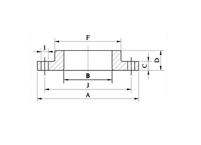
|
Normal Pipe Size (NPS)
|
A
|
B
|
I
|
Holes
|
C
|
D
|
F
|
G
|
Weight In KG
|
|
22″
|
750
|
563.6
|
35
|
20
|
46
|
80
|
610
|
641
|
72.66
|
|
26″
|
870
|
665.2
|
35
|
24
|
68.5
|
90
|
724
|
749
|
120.47
|
|
28″
|
925
|
716
|
35
|
28
|
71.5
|
95
|
781
|
800
|
136.16
|
|
30″
|
985
|
766.8
|
35
|
28
|
74.5
|
100
|
832
|
857
|
161.04
|
|
32″
|
1060
|
817.6
|
41
|
28
|
81
|
106
|
889
|
914
|
205.07
|
|
34″
|
1110
|
868.4
|
41
|
32
|
82.5
|
110
|
940
|
965
|
216.76
|
|
36″
|
1170
|
919.2
|
41
|
32
|
90.5
|
120
|
997
|
1022
|
265
|
|
38″
|
1240
|
970
|
41
|
32
|
87.4
|
120
|
1060
|
1073
|
297.15
|
|
40″
|
1290
|
1020
|
41
|
36
|
90.5
|
125
|
1111
|
1124
|
319.65
|
|
42″
|
1345
|
1071.6
|
41
|
36
|
97
|
130
|
1168
|
1194
|
363.84
|
|
44″
|
1405
|
1122.4
|
41
|
40
|
102
|
136
|
1219
|
1245
|
414.1
|
|
46″
|
1455
|
1173.2
|
41
|
40
|
103
|
144
|
1270
|
1295
|
437
|
|
48″
|
1510
|
1224
|
41
|
44
|
108
|
150
|
1327
|
1359
|
484.52
|
|
50″
|
1570
|
1274.8
|
48
|
44
|
111
|
160
|
1378
|
1410
|
521.23
|
|
52″
|
1625
|
1325.6
|
48
|
44
|
116
|
170
|
1435
|
1460
|
581.51
|
|
54″
|
1685
|
1376.4
|
48
|
44
|
121
|
178
|
1492
|
1511
|
652.63
|
|
56″
|
1745
|
1427.2
|
48
|
48
|
124
|
188
|
1540
|
1575
|
713.31
|
|
58″
|
1805
|
1478
|
48
|
129
|
195
|
1590
|
1626
|
799.81
|
|
|
60″
|
1855
|
1528.8
|
48
|
52
|
132
|
200
|
1657
|
1676
|
836.15
|
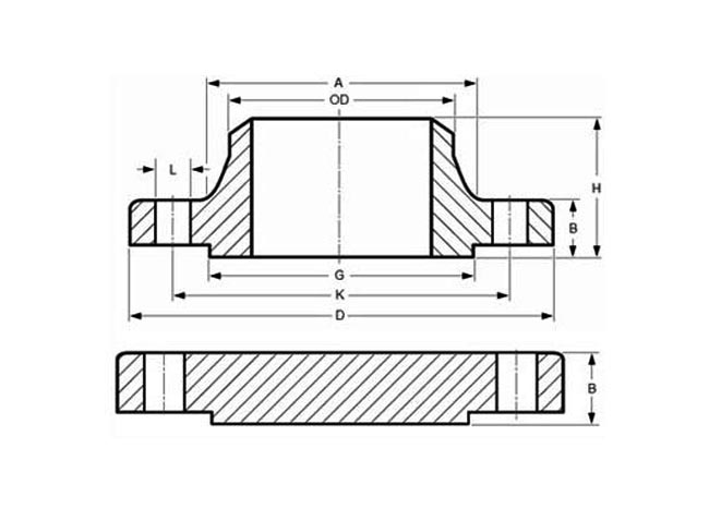
|
Thickness Of Blind Flanges
|
Drilling
|
Weight In Kilogram
|
|||||||||||
|
NPS
|
Outside Daimeter (O.D.)
|
WNRF (Weld Neck)
|
BLRF (Blind)
|
Outside Daimeter of Raised Face
|
Base Daimeters
|
LTH
|
Bevel Daimeters
|
Bolts Circle
|
Bolts Length
|
Holes Daimeters
|
# of Holes
|
Weld Neck Flanges
|
Blind Flanges
|
|
O
|
C
|
C
|
R
|
X
|
Y
|
A
|
(1)
|
(2)
|
|||||
|
26
|
34.25
|
2.63
|
2.63
|
29.5
|
26.62
|
4.69
|
26
|
31.75
|
8.75
|
1.38
|
24
|
300
|
702
|
|
28
|
36.5
|
2.75
|
2.75
|
31.5
|
28.62
|
4.88
|
28
|
34
|
9
|
1.38
|
28
|
345
|
833
|
|
30
|
38.75
|
2.88
|
2.88
|
33.75
|
30.75
|
5.32
|
30
|
36
|
9.25
|
1.38
|
28
|
400
|
982
|
|
32
|
41.75
|
3.13
|
3.13
|
36
|
32.75
|
5.63
|
32
|
38.5
|
10.5
|
1.62
|
28
|
505
|
1237
|
|
34
|
43.75
|
3.19
|
3.19
|
38
|
34.75
|
5.82
|
34
|
40.5
|
10.5
|
1.62
|
32
|
540
|
1384
|
|
36
|
46
|
3.5
|
3.5
|
40.25
|
36.75
|
6.13
|
36
|
42.75
|
11
|
1.62
|
32
|
640
|
1676
|
|
38
|
48.75
|
3.38
|
3.38
|
42.25
|
39
|
6.13
|
38
|
45.25
|
11
|
1.62
|
32
|
720
|
1819
|
|
40
|
50.75
|
3.5
|
3.5
|
44.25
|
41
|
6.38
|
40
|
47.25
|
11
|
1.62
|
36
|
775
|
2040
|
|
42
|
53
|
3.75
|
3.75
|
47
|
43
|
6.69
|
42
|
49.5
|
11.5
|
1.62
|
36
|
890
|
2381
|
|
44
|
55.25
|
3.94
|
3.94
|
49
|
45
|
6.94
|
44
|
51.75
|
12
|
1.62
|
40
|
990
|
2717
|
|
46
|
57.25
|
4
|
4
|
51
|
47.12
|
7.25
|
46
|
53.75
|
12
|
1.62
|
40
|
1060
|
2961
|
|
48
|
59.5
|
4.19
|
4.19
|
53.5
|
49.12
|
7.5
|
48
|
56
|
12.5
|
1.62
|
44
|
1185
|
3348
|
|
50
|
61.75
|
4.32
|
4.32
|
55.5
|
51.25
|
7.94
|
50
|
58.25
|
13.25
|
1.88
|
44
|
1270
|
3716
|
|
52
|
64
|
4.5
|
4.5
|
57.5
|
53.25
|
8.19
|
52
|
60.5
|
13.75
|
1.88
|
44
|
1410
|
4156
|
|
54
|
66.25
|
4.69
|
4.69
|
59.5
|
55.25
|
8.44
|
54
|
62.75
|
14
|
1.88
|
44
|
1585
|
4639
|
|
56
|
68.75
|
4.82
|
4.82
|
62
|
57.38
|
8.94
|
56
|
65
|
14.25
|
1.88
|
48
|
1760
|
5132
|
|
58
|
71
|
5
|
5
|
64
|
59.38
|
9.19
|
58
|
67.25
|
14.75
|
1.88
|
48
|
1915
|
5675
|
|
60
|
73
|
5.13
|
5.13
|
66
|
61.38
|
9.38
|
60
|
69.25
|
15
|
1.88
|
52
|
2045
|
6154
|
| Normal Pipe Size (NPS) | d1 Inside Daimeter (I.D.) | d2 Outside Diameter (O.D. Of Gasket) | |||
| 150 LB | 300 LB | 400 LB | 600 LB | ||
| 26 | 660 | 775 | 835 | 832 | 867 |
| 28 | 711 | 832 | 899 | 892 | 914 |
| 30 | 762 | 883 | 953 | 946 | 972 |
| 32 | 813 | 940 | 1006 | 1003 | 1022 |
| 34 | 864 | 991 | 1057 | 1054 | 1073 |
| 36 | 914 | 1048 | 1118 | 1118 | 1130 |
| 38 | 965 | 1111 | 1054 | 1073 | 1105 |
| 40 | 1016 | 1162 | 1114 | 1127 | 1156 |
| 42 | 1067 | 1219 | 1165 | 1178 | 1219 |
| 44 | 1118 | 1276 | 1219 | 1232 | 1270 |
| 46 | 1168 | 1327 | 1273 | 1289 | 1327 |
| 48 | 1219 | 1384 | 1324 | 1346 | 1391 |
| 50 | 1270 | 1435 | 1378 | 1403 | 1448 |
| 52 | 1321 | 1492 | 1429 | 1454 | 1499 |
| 54 | 1372 | 1549 | 1492 | 1518 | 1556 |
| 56 | 1422 | 1607 | 1543 | 1568 | 1613 |
| 58 | 1473 | 1664 | 1594 | 1619 | 1664 |
| 60 | 1524 | 1715 | 1645 | 1683 | 1721 |